![]()
902 MHz Transverter Construction
The IF frequency is 432 MHz. A 470 MHz LO is generated by a Silicon Labs Si530 chip. The differential outputs each drive a RFMD/Sirenza SGA-6386. Each buffered LO output drives a Minicircuits mixer. A ZFM-150 (level 10, low conversion loss) is used in the receive path and a ZX01-U432H-S is used in the up-conversion transmit path.
The receiver front-end consists of a Minicircuits 0.55 dB NF LNA, ZX60-0916LN-S, and a two resonator BPF preselector. The preselector was constructed from 0.25" wide brass strips in a Hammond Aluminum housing. Insertion loss is 0.5 dB in the 20 MHz passband. Following the ZFM-150 mixer is a matched band pass equalizer centered at 432 MHz.
The transmit circuit following the up conversion mixer is a two resonator BPF. This filter is identical to the receive preselector. A Toshiba S-AU86 driver module drives a single 150W PA strip. This power amplifier was removed from a Motorola cellular SGTF-1019. An integrated isolator is provided by this version of Motorola PA. The 432 MHz IF signal is attenuated by a 30 dB power pad.
RF switching is provided by three, latching type 12V, SPDT SMA coaxial relays. Pulsed driver circuits for relay switching, sequencing, and switched bias circuits are all accomplished with self contained analog circuitry. When the transverter is in the OFF position the IF radio is switched to a UHF antenna port on the rear panel. A single +24V power supply is required for operation.
![]()
902 Transverter - Top
![]()
902 Transverter - Rear
![]()
902 Transverter - Right Rear
![]()
902 Transverter - Right Front
![]()
902 Transverter - PA panel
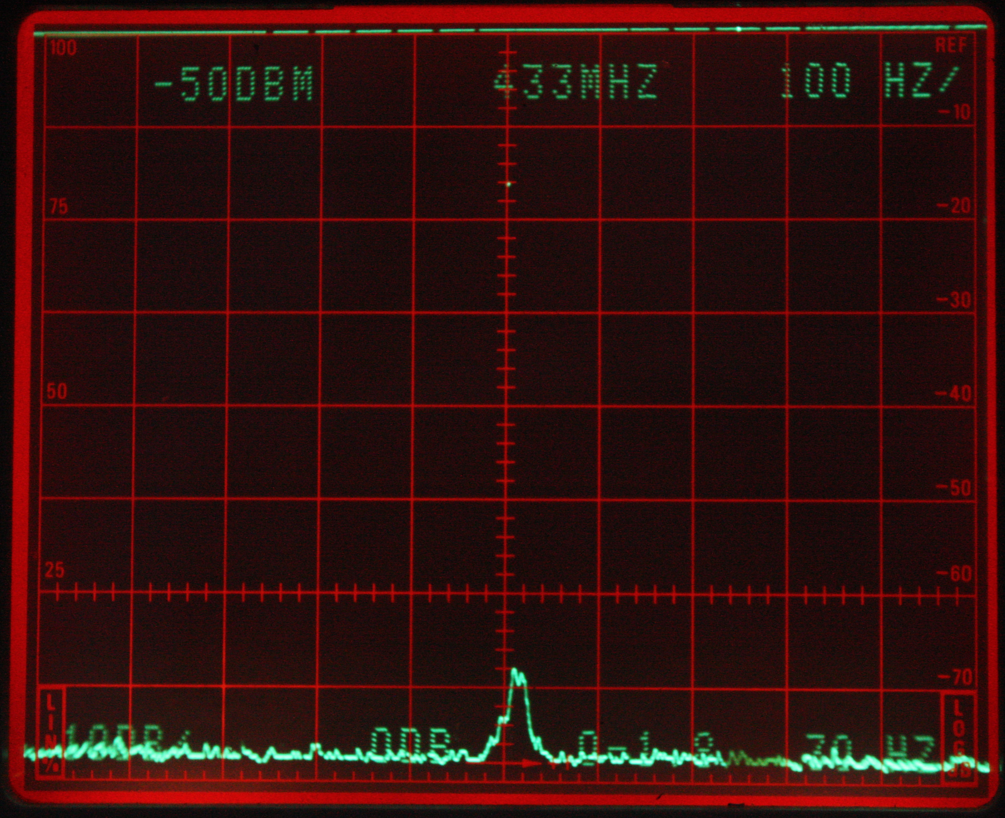
432 MHz IF Response to a 0.1uV 902 MHz Signal