Transverter
10 GHz Transverter Construction
The IF frequency is 50 MHz for an RF frequency of 10,368.0 MHz. A 644.8750 MHz reference is generated by a Silicon Labs Si530 chip. The output of the Si530 is multiplied x16 with a Hittite HMC445LP4E chip to yield an output level of +4 dBm. This is buffered by a pad and an AML amplifier to yield an output level of +13 dBm. The LO output from the multiplier is on 10,318.000 MHz.The LO signal is filtered with a Farinon 4 pole evanescent mode WG BPF, followed by an isolator and a coaxial relay. The coaxial relay routes the LO to either the transmit or receive double ballanced mixer. These are SMA connectorized Magnum Microwave mixers. I measured conversion loss vs LO level. It knee is approximately +3 dBm with a conversion loss of 7dB. If the LO level is increased to +4 or +5 dBm, the conversion loss remains virtually unchanged. These mixers are used in both the receive path and the up-conversion transmit path.
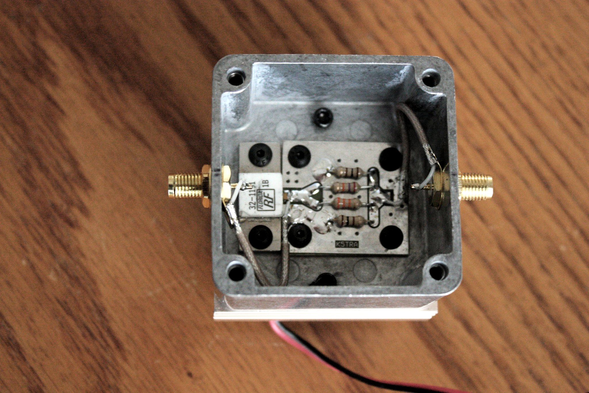
The receiver front-end consists of a homebrew pHEMT LNA, When I say homebrew, I mean even the PC board patterning and etching was done at home. NEC-CEL NE3512S02 pHEMTS were used in both stages on Rogers R04003 20 mil, material. I was able to get 18 dB gain and 2 dB NF. That's not as low as I hoped; but, not surprising from poor linewidth control and wire through holes.
Between the receive mixer and LNA are an AML amplifier (+17dB), Farinon 4 pole WG filter and Harris isolator. The IF port of the receive mixer drives a Sirenza SGA6486 post amplifier followed by a pi pad. The post amp and receive pad reside on the sequencer-controller board. During early rising edge IF power, the receive mixer and post amp are protected by a shunt PIN that is biased on (and a schottky) across the post amp side of the pi pad. This clamping low impedance greatly increases the pad attenuation from 8 dB to near 40 dB. Simultaneously, the T/R relays are switched.
The IF drive from the 6M transceiver is detected by a (tuned to 6M) schottky detector on the sequencer-controller board. This controls the relay switching and switched +12V to transmitter and receiver circuits.
The transmitter PA is homebrew and yields a linear output power of 12W. The PA uses a Triquint/Qorvq GaN packaged MMIC and a homebrew bias sequencer board with negative gate bias charge-pump and regulator. The PA is driven by the followinf line-up: a 25 dBm Harris amplifier, Farinon 4 pole WG filter, Harris isolator and transmit mixer. The IF port of yhe transmit mixer is driven by approximately -5 dBm from a power attenuator that dissipates the 6M IF transceiver's output.
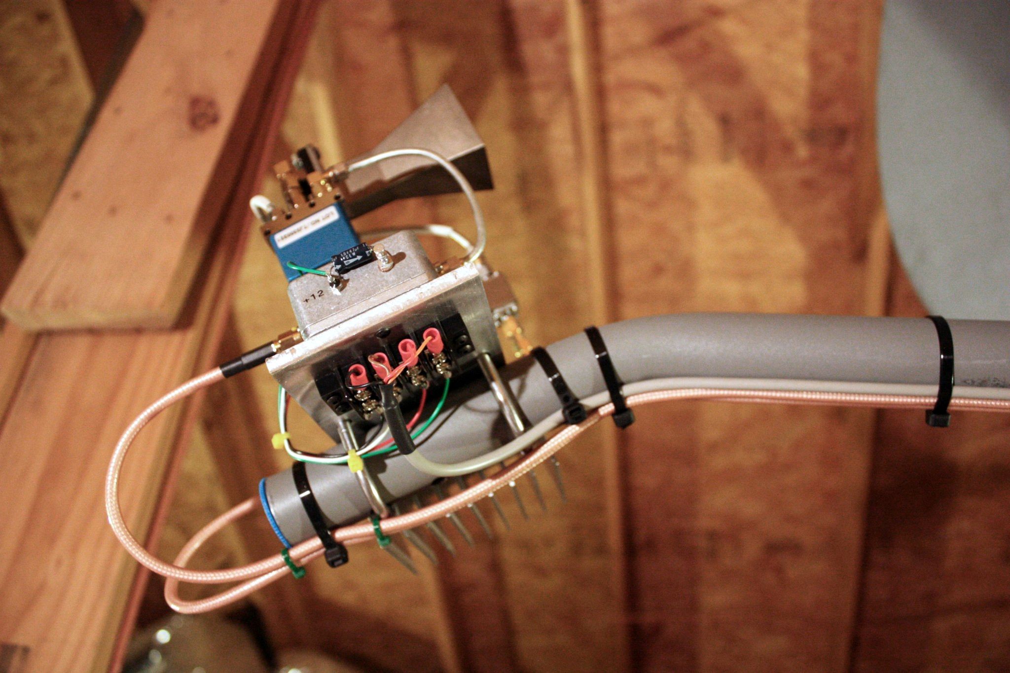
Both the LNA and PA are located with a SMA coaxial relay at the dish horn-feed.
When the transverter is in the OFF position the IF 6M radio is switched to the 6M antenna port on the rear panel. A single +12V power supply is required for operation. This is controlled remotely through my home network.
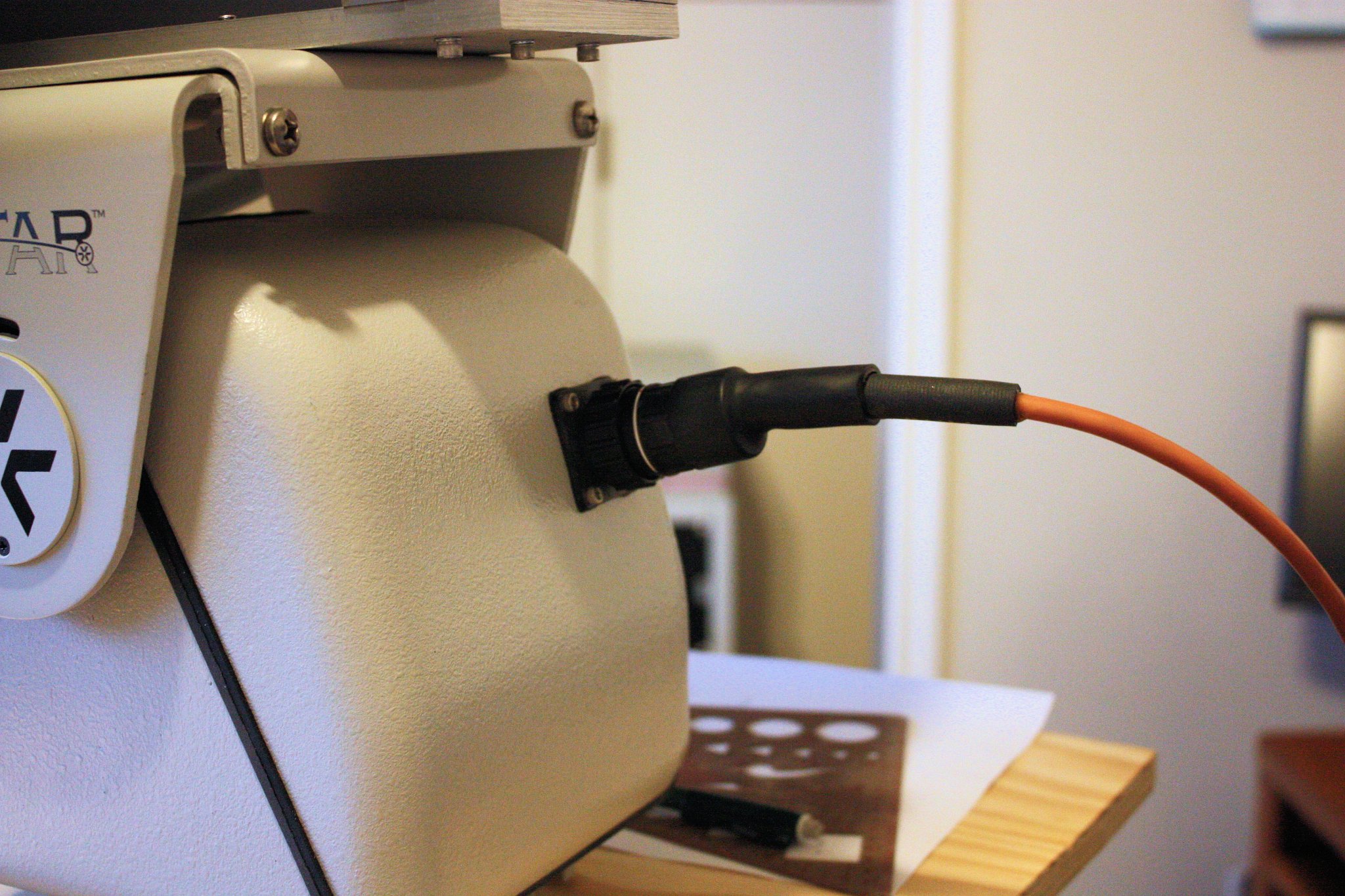
The azimuth-elevation positioning of the dish is also controlled through my home network.I have constructed "control" and "remote receiver" units to allow me to steer the dish from the shack. The AZ-EL positioner is a VICON "ViStar" pan-tilt remote camera positioner capable of handling a 35 lb. load.
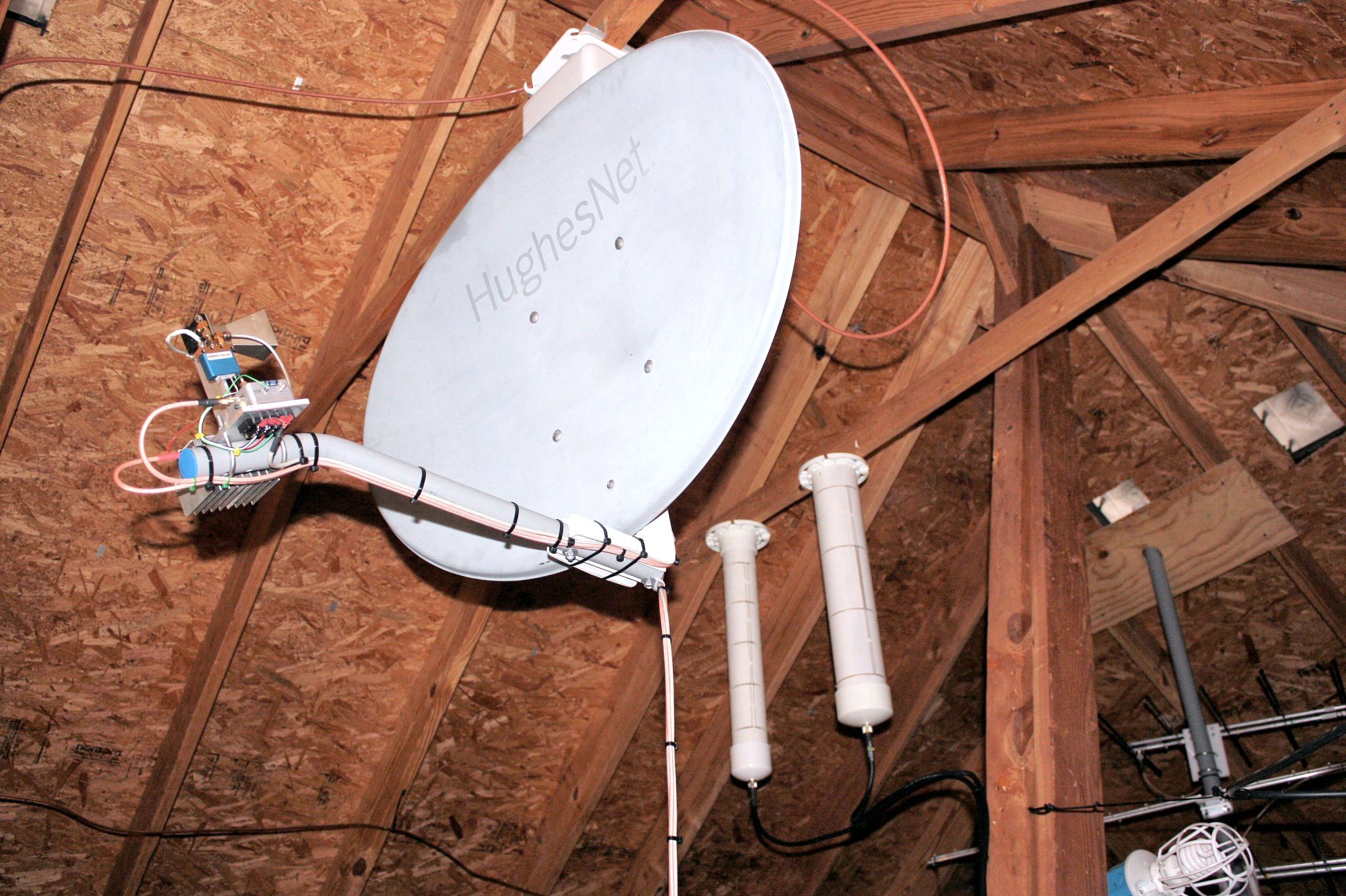
I have NO wind loading since the dish is mounted in the attic of my house. I have found the loss through the roof to be minimal. In fact, two days after the 10 GHz station went operational, we had good propagation early in the morning and I was able to work W5LUA on CW. That is 213 miles! Other 'local' QSO's out to 50 miles are routine. I have a very good location and attribute a large portion of my success with hidden antennas, to the location.
10 GHz Transverter - Top
10 GHz Transverter - Front
10 GHz Transverter - Rear
10 GHz Transverter - Rear (zoomed)
10 GHz Transverter - Block Diagram (click for PDF)
10 GHz Transverter - Gain & Power Budget
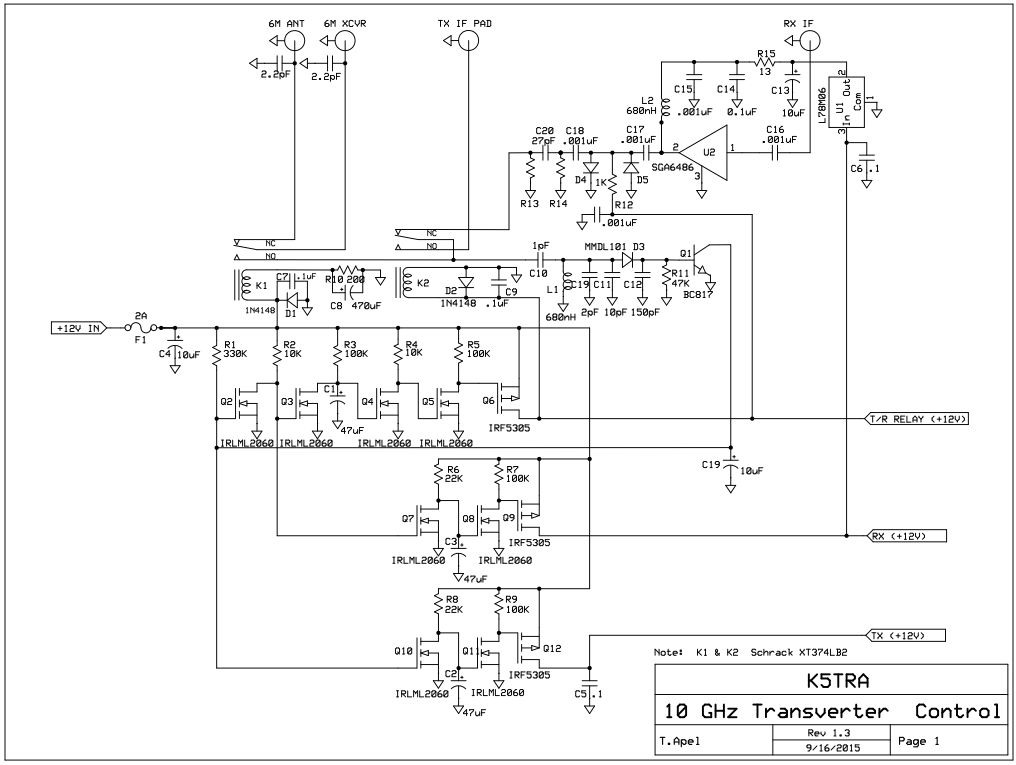
Sequencer-Controller - Schematic (click for PDF)
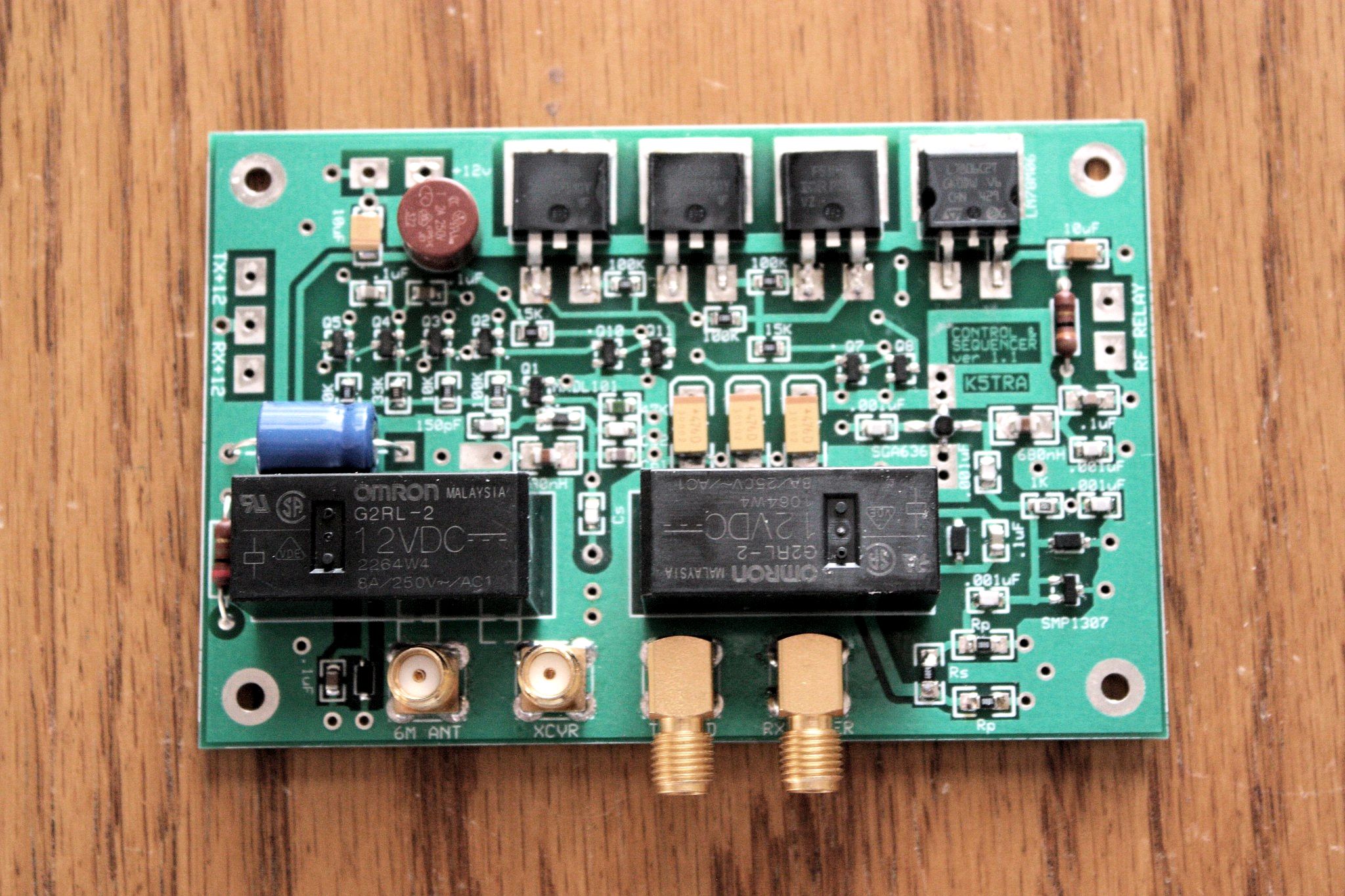
Sequencer-Controller Board - Front
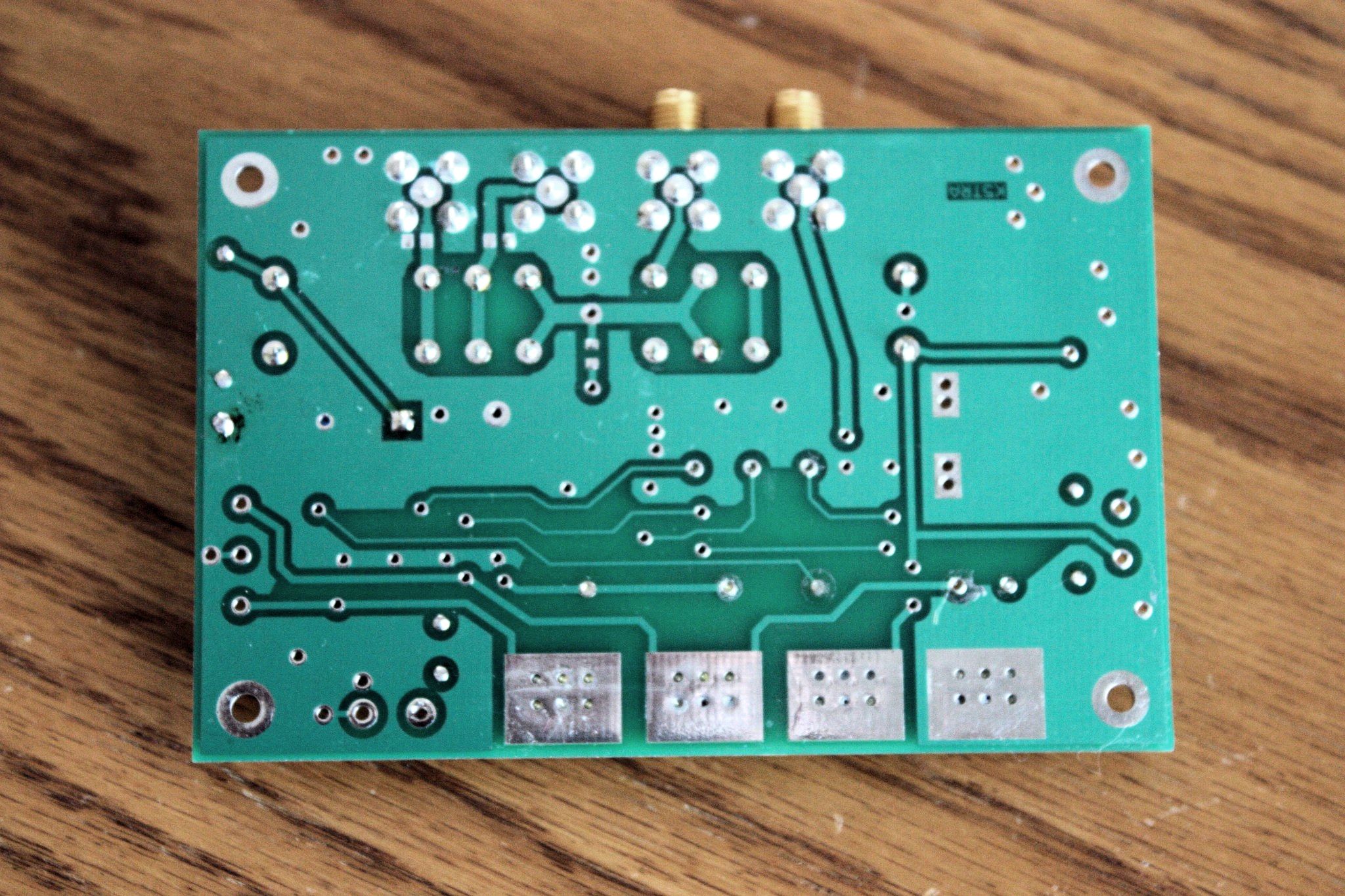
Sequencer-Controller Board - Rear
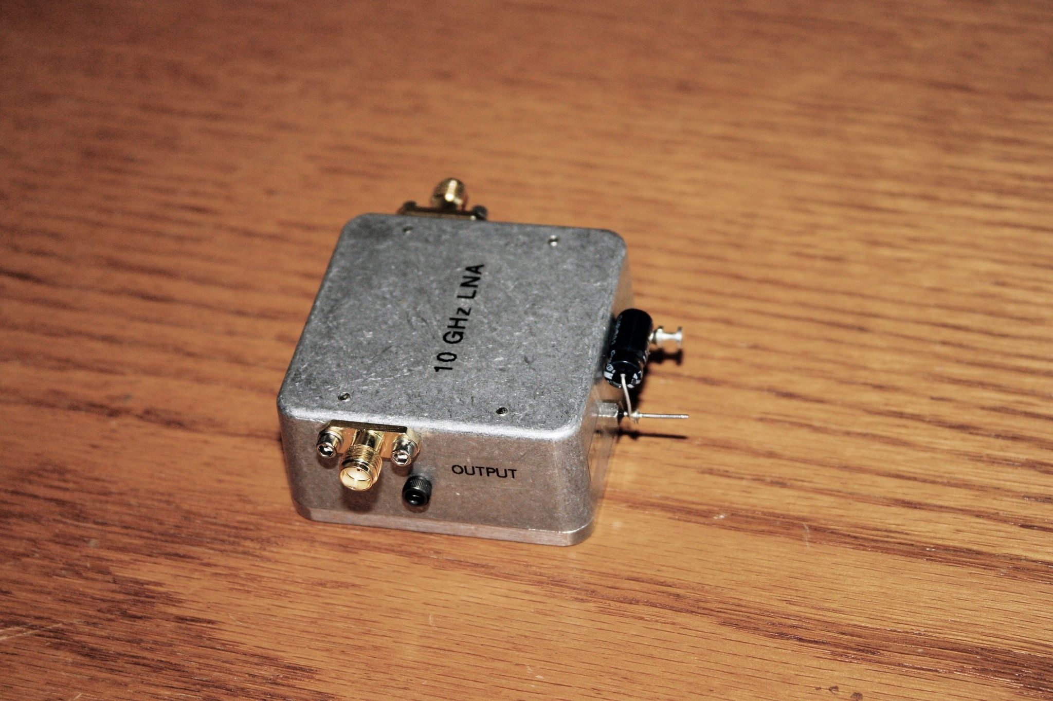
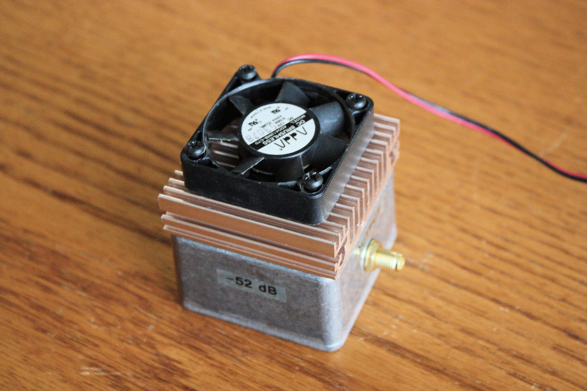
LNA - External
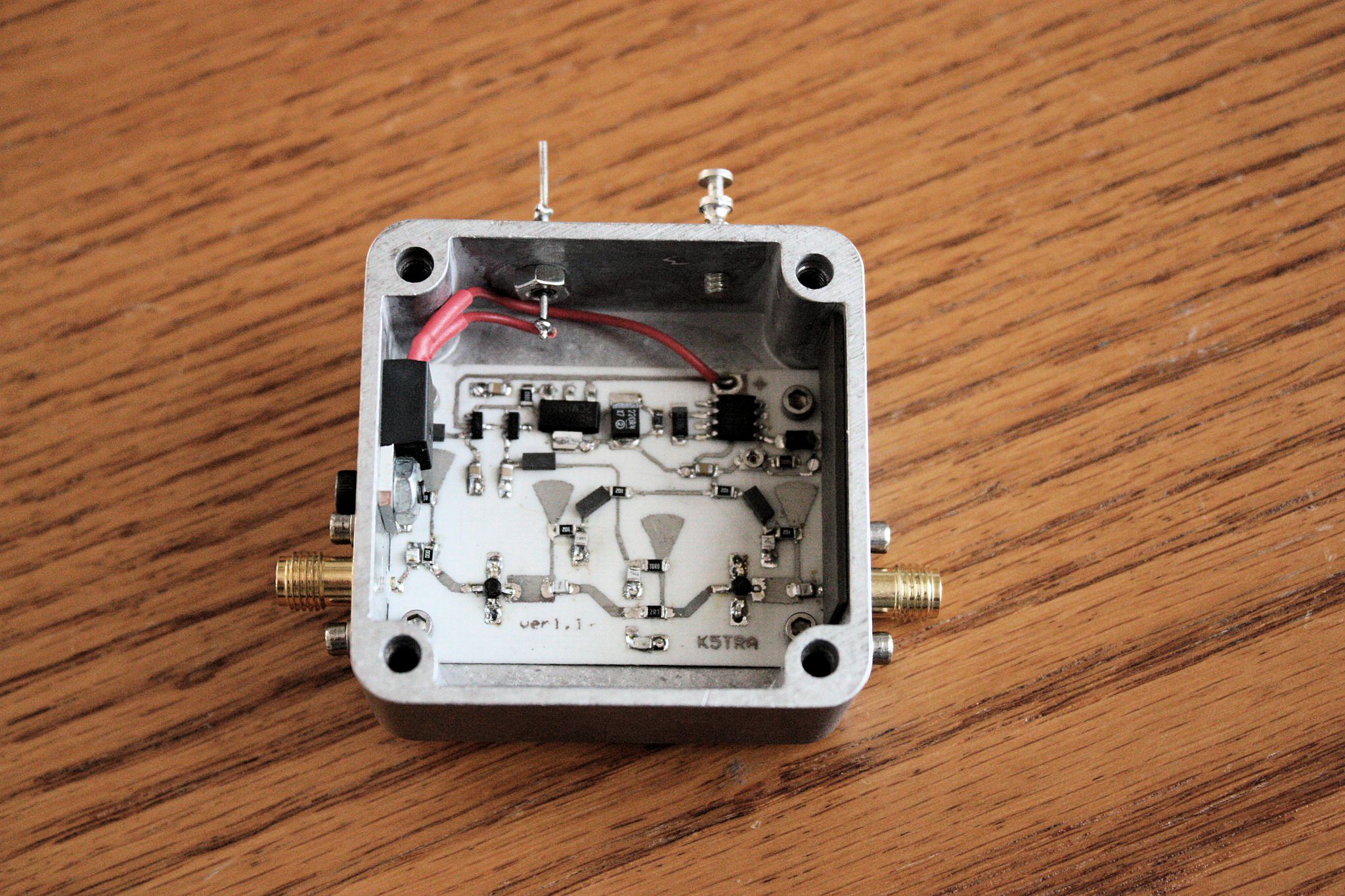
LNA - Internal (click for design info)
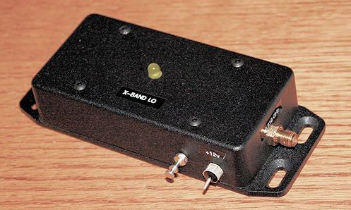
LO x16 - External
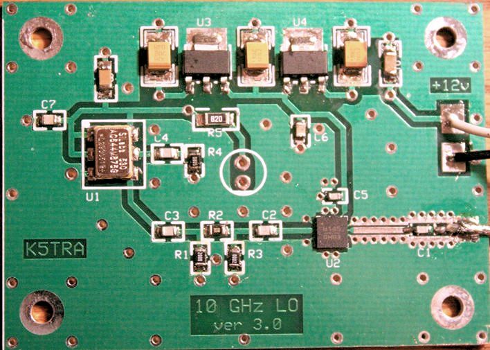
LO x16 board (click for schematic)
IF Power Pad - External
IF Power Pad - Internal
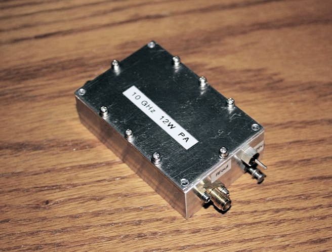
12W PA - External
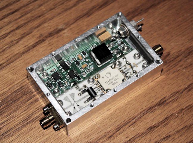
12W PA - Internal (click for design info)
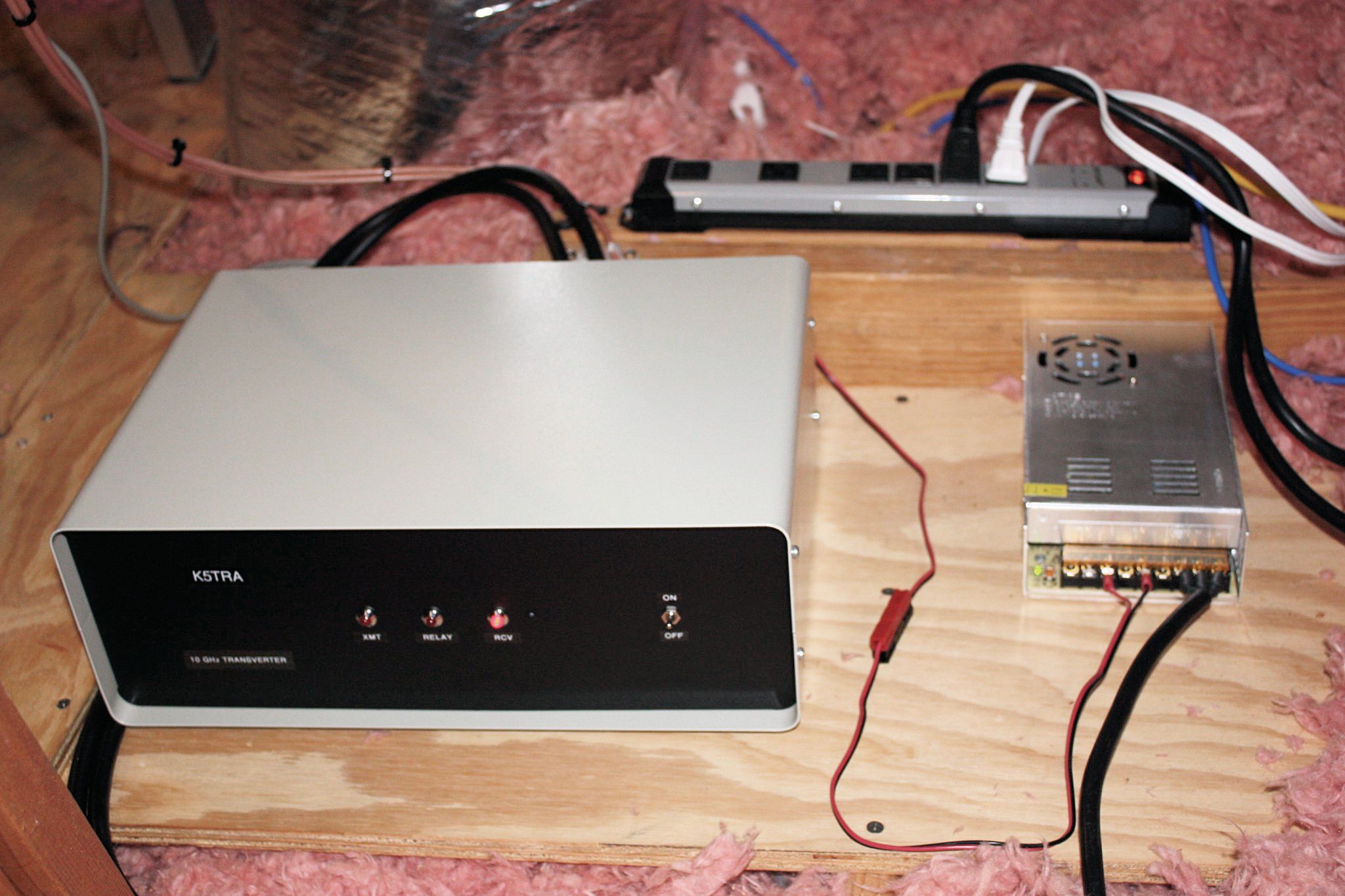
Remote Transverter (in attic)
Dish-Feed and Positioner
Offset-feed Analysis and AZ-EL Positioner
I was fortunate to get a VSAT dish from a friend, NO5K. The original feed was missing; so, I needed to do some analysis to find the focal point and horn pointing angle. I documented this in a PDF that can be downloaded. All parabolas are similar. They only differ by a scaling constant that determines the relative curvature and f/D (ie, how shallow or deep the dish). Dish reflectors, with a single reflector surface, are usually defined by the intersection of a paraboloid and a plane.With Axial feed dishes, the intersecting plane is perpendicular to the focal axis.Offset feed dishes are usually defined by the intersecting plane cutting through the origin; so, it is asumed that the boresight direction is along a line from the bottom of the dish to the horn feed. This distance is F in my analysis. The focal distance from the top (center) of the dish is Fe in my analysis. Only two measurements are needed to solve the feed geometry. They are: (1) the width of the dish along the center line (from top to bottom), and (2) the depth of the dish in the center. the analysis shows that this always occurs in the same place for all paraboloid sections. The horn pointing angle and effective f/D are also calculated.
I am using a VICON - ViStar remote camera "pan-tilt" positioner for azimuth and elevation positioning. I have the VIST35 model that operates from 24VAC applied to various pins on the control connector. My home network is used to send commands to the remote positioner. Spring loaded "center-off" SPDT toggle switches are used to control the two axes (CW-CCW and UP-DOWN). Five volts is switched to inputs of a "Five Input Module" from ControlByWeb. This defines the sender unit in the radio shack. The network receiver unit, in the attic, contains a WebRelay Quad (also made by ControlByWeb) to switch 24VAC to the correct pins in the ViStar positioner.
The azimuth end points are set to known reference directions. I have characterised the rotation rate (degrees/sec); so the time from one bearing to another can be tabulated in a chart. I also use a web camera for visual confirmation on pointing direction of the dish.
Offset-feed (1 meter x 2/3 meter) Dish -- hanging in my attic
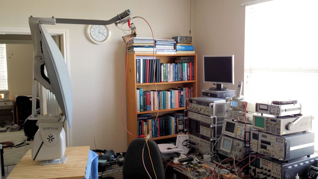
Bench-testing Dish, Positioner, & Receiver (listening to NO5K beacon through window)
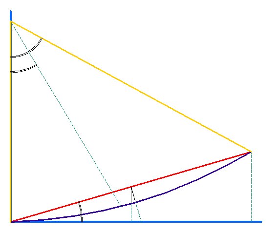
Offset-Feed Calculations for Dish (click for PDF)
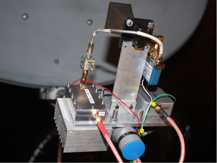
Focal Plane Hardware
Focal Plane Hardware - another view
Azimuth-Elevation Positioner
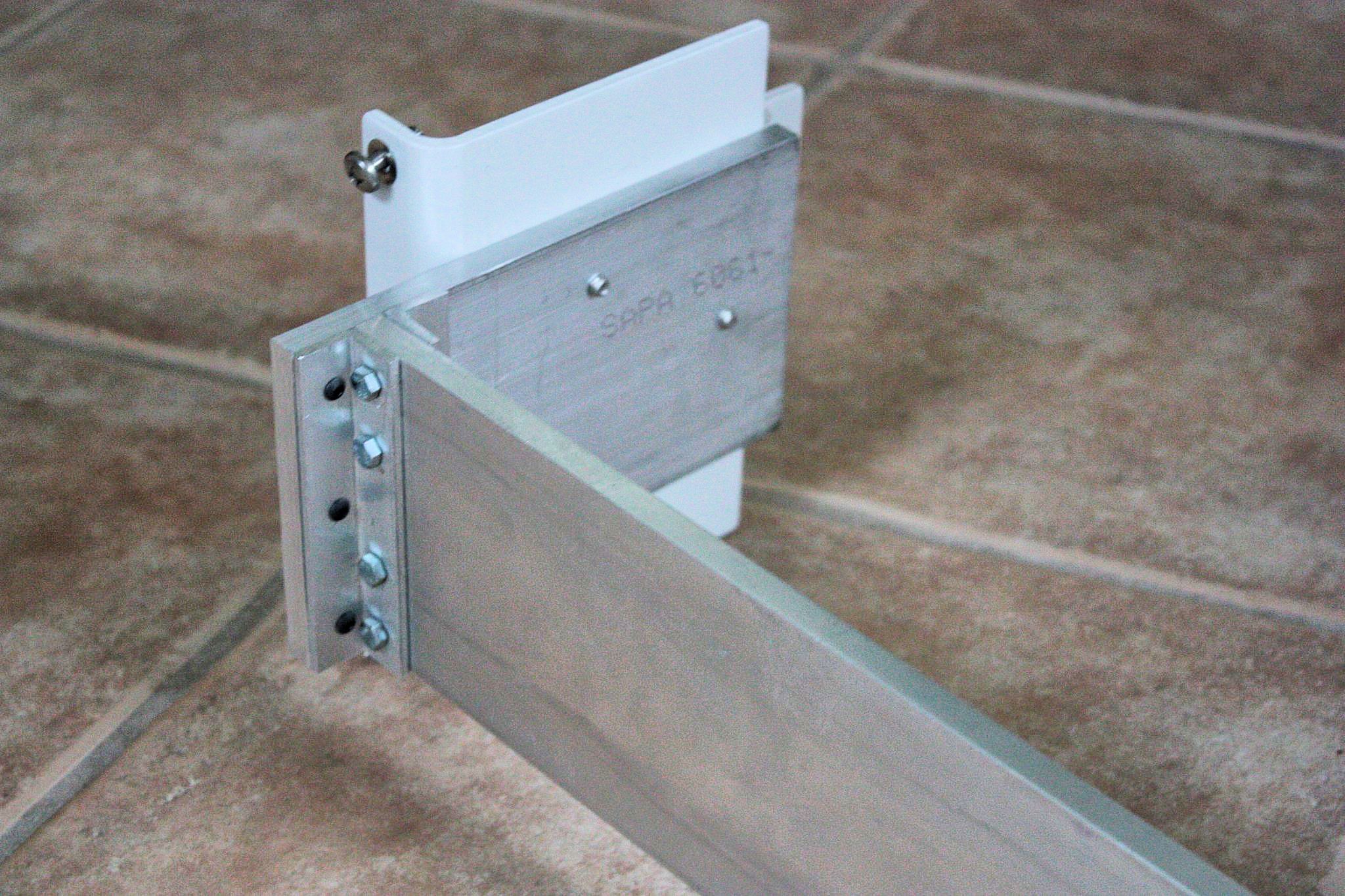
Dish Mounting Bracket
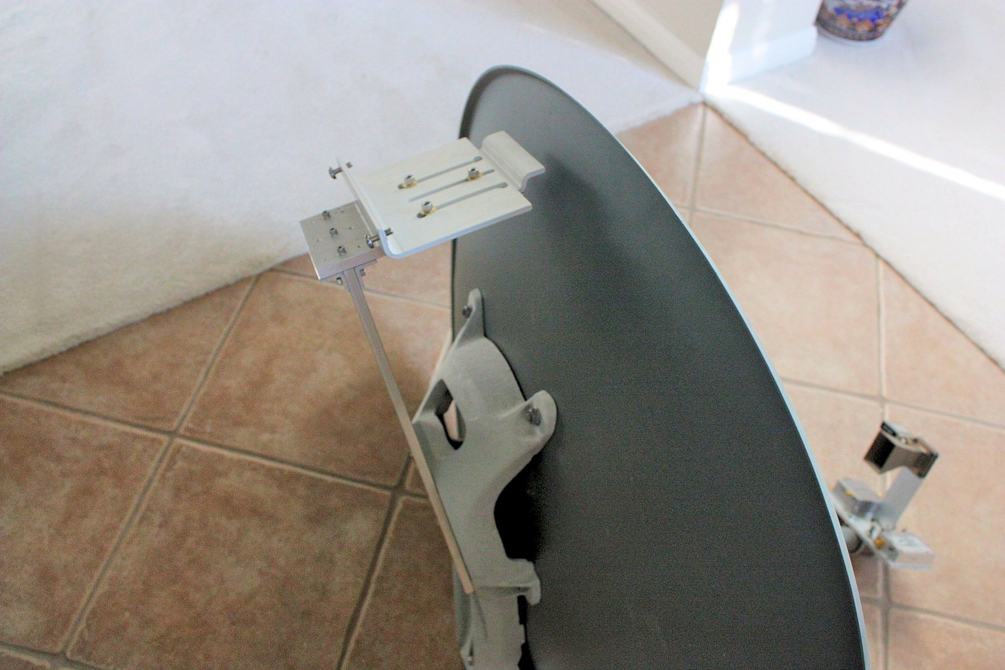
Mounting Bracket - Attached to Dish
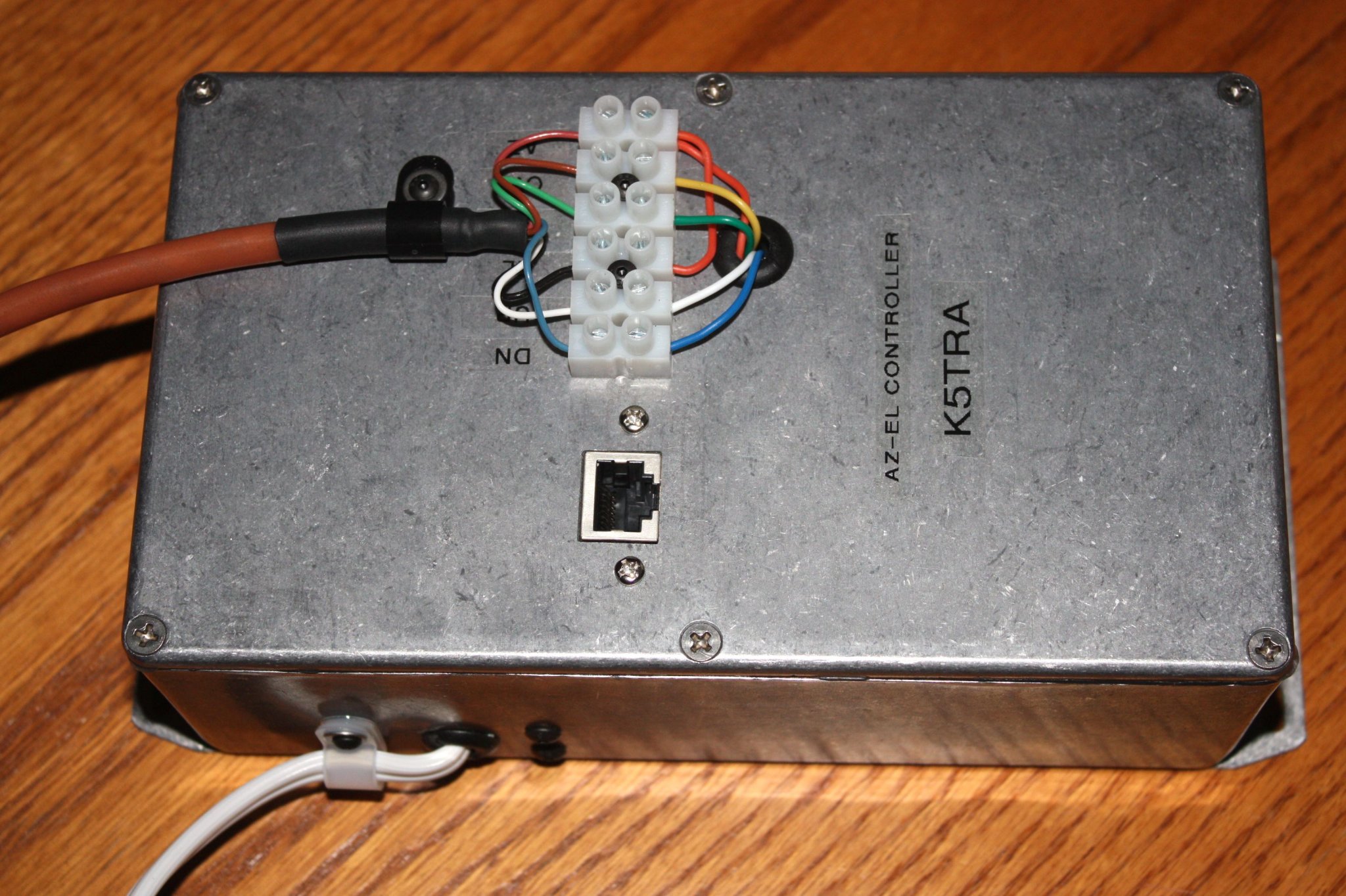
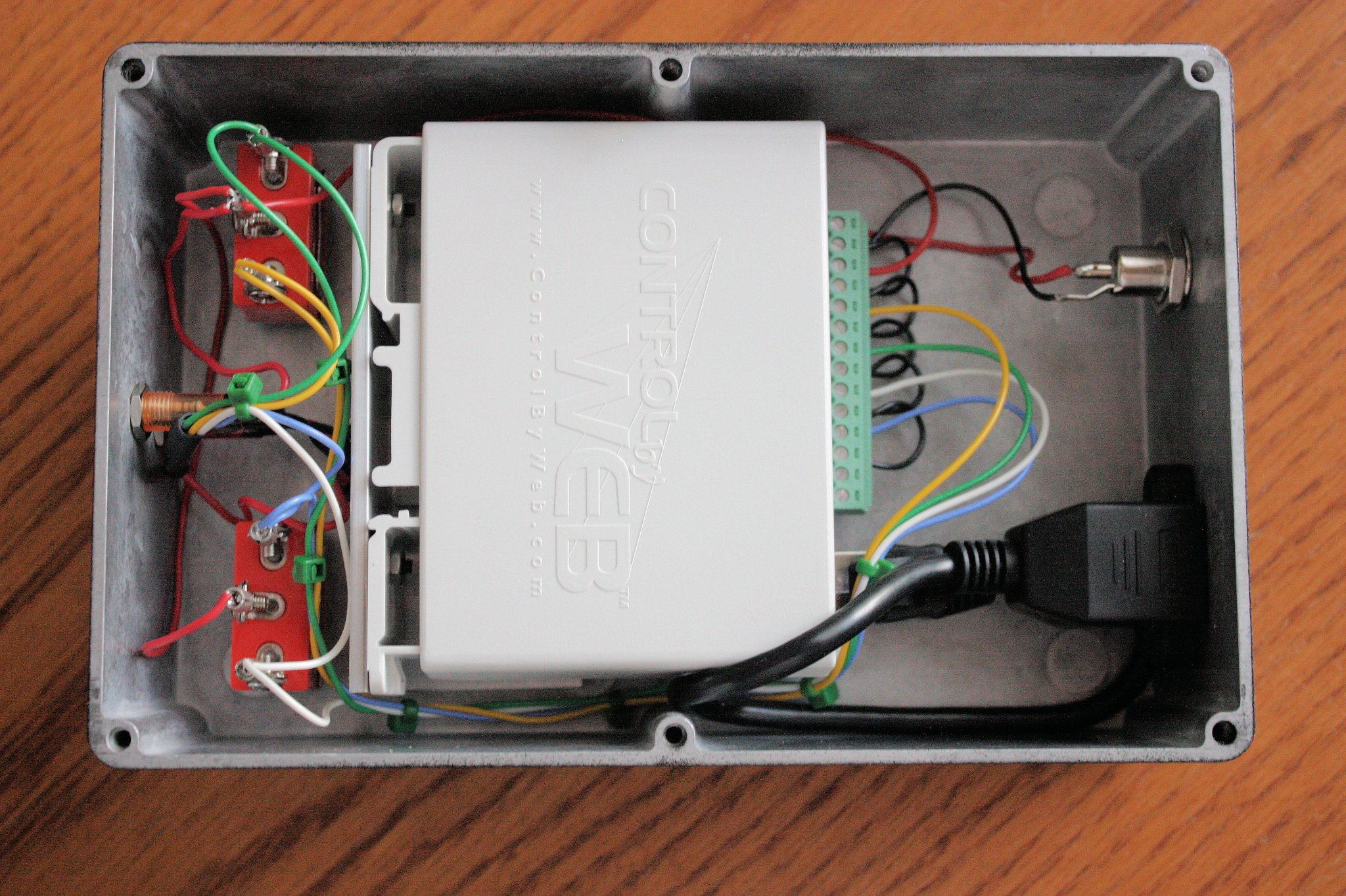
Remote Controller for AZ-EL Positioner (network interface)
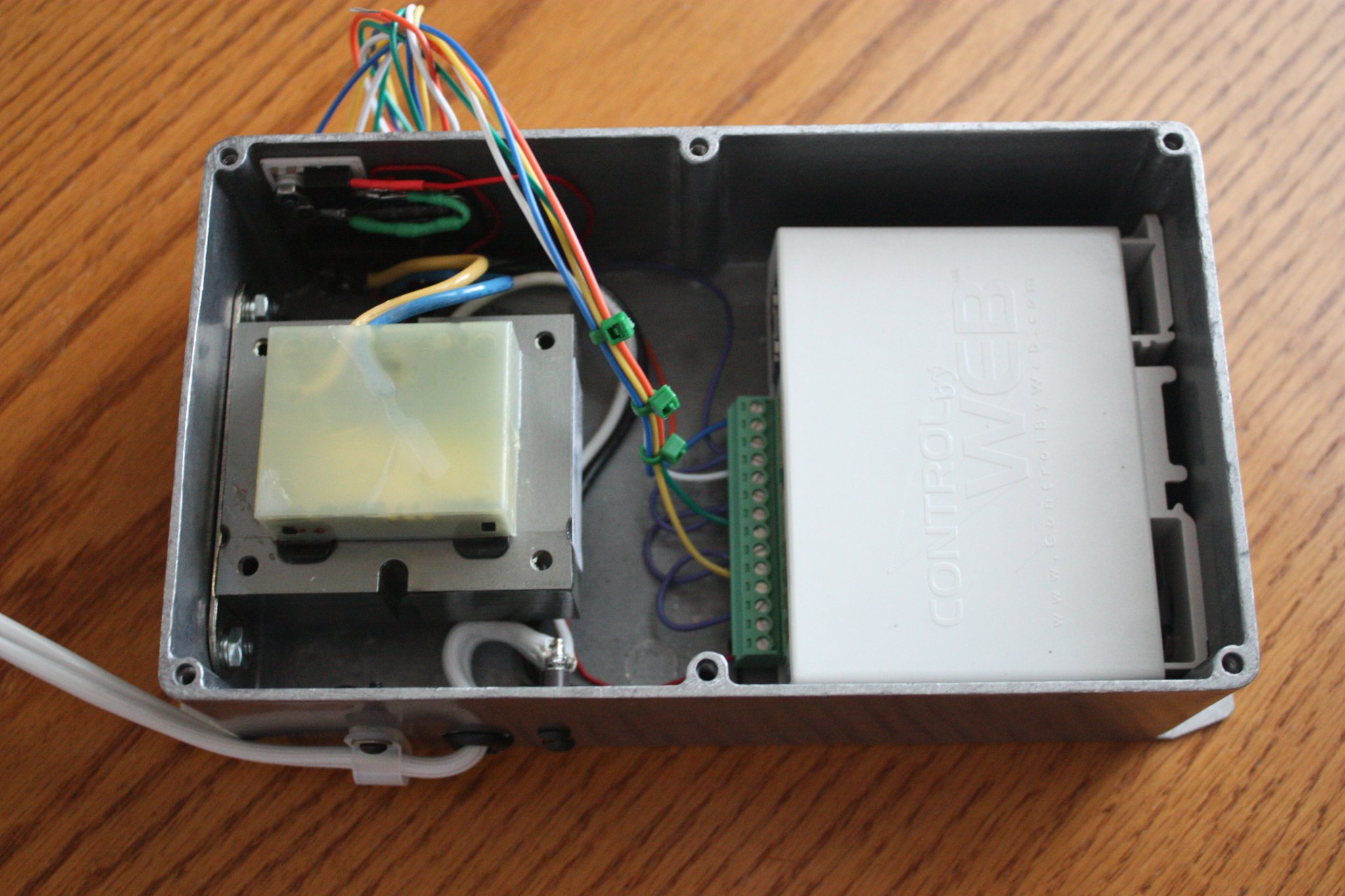
Remote Controller (interior)
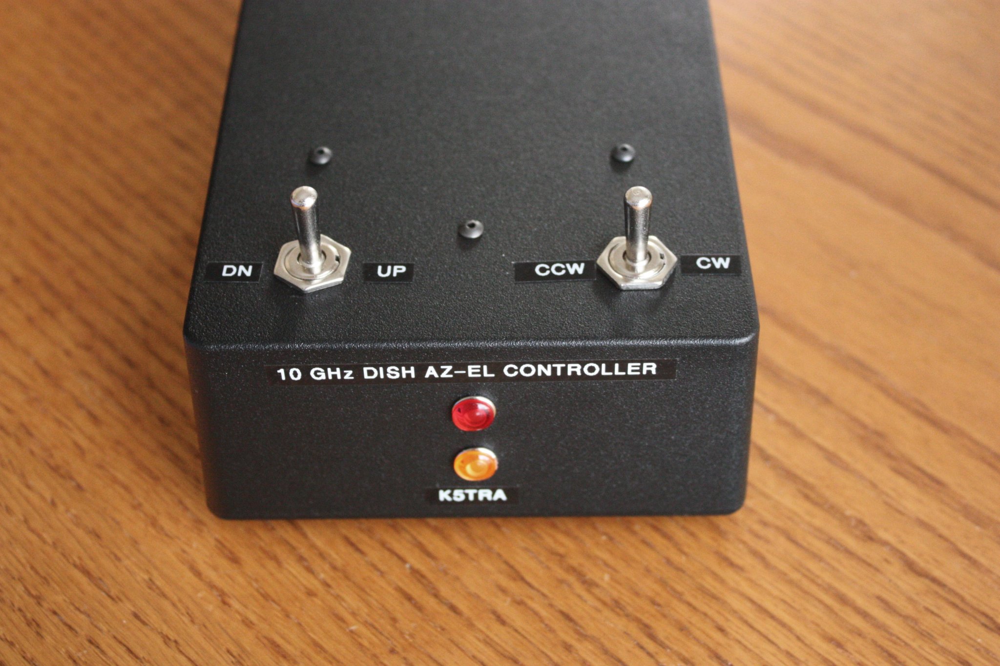
In-Shack Interface for AZ-EL Positioner - Front
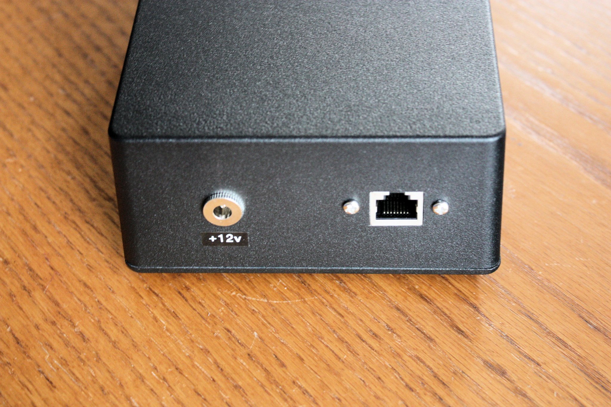
In-Shack Interface for AZ-EL Positioner - Rear
In-Shack Interface for AZ-EL Positioner (interior)
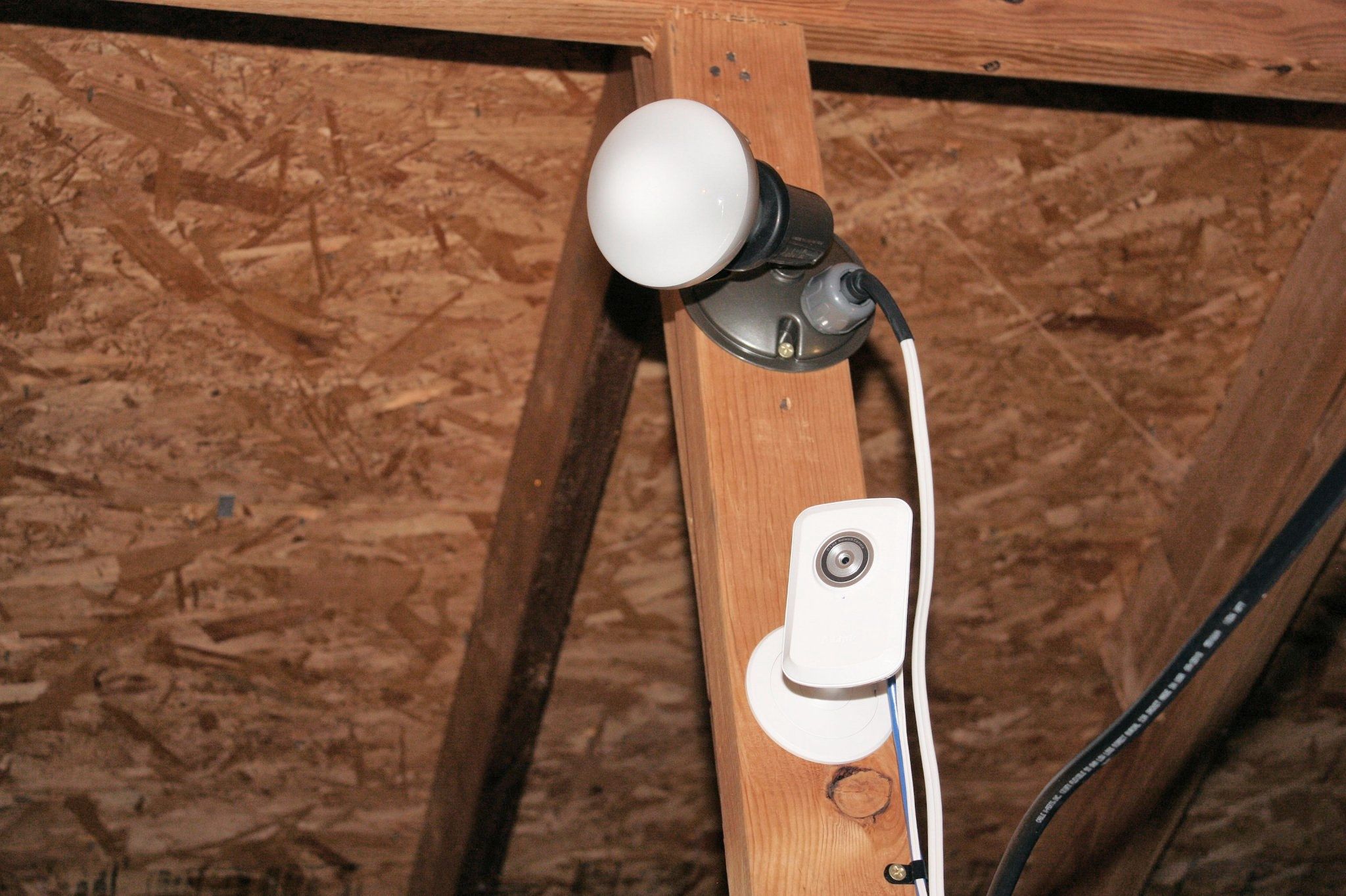
Network Camera (to aid in pointing dish)
Instrumentation for 10 GHz (on a home budget)
10 GHz Instrumentation
When I decided to start on a 10 GHz radio capability, the first challenge was to be able to measure signals at X-band: power, gain/loss, reflection, frequency, etc. I had instrumentation that works well through 1296 MHz; but, nothing above 2 GHz with the exception of an HP432A power meter.
My first project was a "Test-Set" that would extend operation of my lower frequency instrumentation to 10 GHz. I used a DRO source for a common LO injected into a pair of up and down conversion mixers. This is essentially an instrumentation transverter. Since conversions are synchronous, an IF signal into the up conversion mixer produces an X-band output that can be down converted by the companion mixer to produce an output at the IF that is synchronous with the original IF signal. Jitter in the DRO is of course present at 10 GHz; but not seen in the recovered IF signal. I used an 11.250 GHz DRO to translate 882 MHz to 10368 MHz. Image reject filters are necessary to prevent errors from a response at 2x IF away from the desired frequency.
I created good wideband image filters from 0.5" Copper pipe. This pipe makes a good circular wave guide with a lower cut-off frequency around 13.8 GHz. Operation below cut-off is reactively lossy and propagation is called evanescent. Sections of evanescent mode wave guide can be represented by a symmetric pi section of inductors. Sections of in-band guide can be made to be evanescent by addition of inductive posts or septums. The familiar Farinon 4-pole filters are examples of this. From a filter realization perspective, sections of evanescent guide represent the basis of admittance inverters. Bandpass filters are realized by cascades of parallel resonators and admittance inverters. Resonators are realized by placing tuning screws in-line with high E-field orientations. A tuning screw causes a parallel capacitance that resonates with the local inductance of the cut-off guide. Design details and tables are provided in a linked PDF.
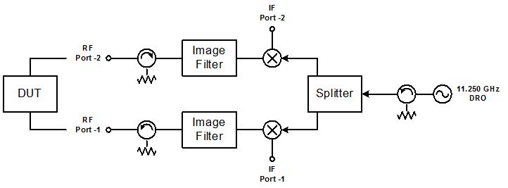
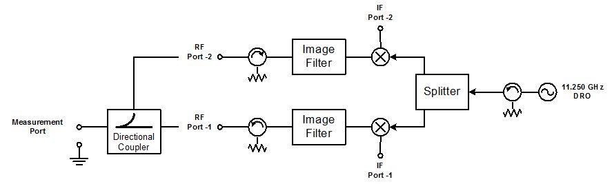
A network analyzer operating at the test set IF frequency provides an easy way to measure gain or loss. Reflection measurements are done with a directional coupler connection to port two of the test set (see diagram, below). Other source and receiver instruments that operate at the IF can be used instead of the network analyzer. For example,a service monitor or other signal generator can be used on the source side and a spectrum analyzer can be used on the receive side to make frequency and relative level measurements.
This test set has enabled me to measure and tune amplifiers, filters, isolators, and pads at 10 GHz.
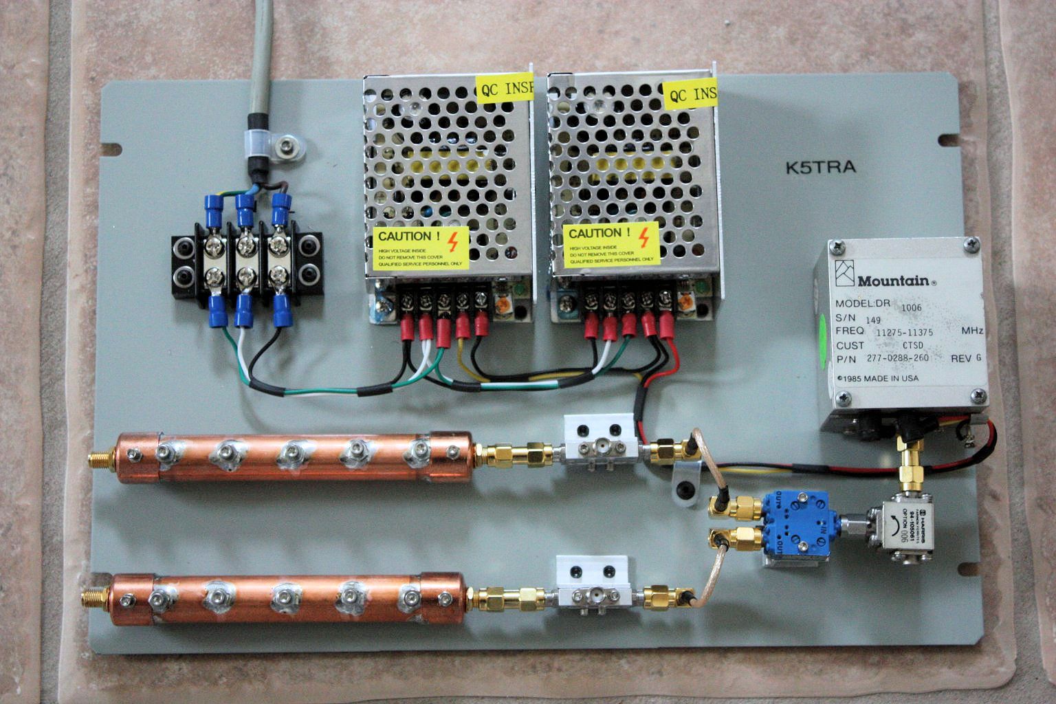
10 GHz Test Set
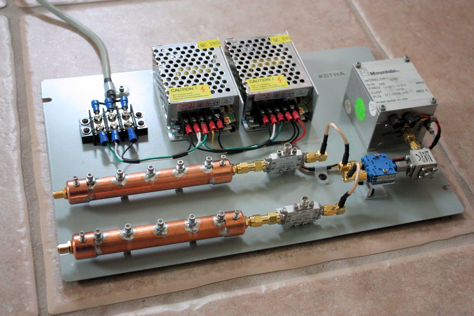
10 GHz Test Set - another view
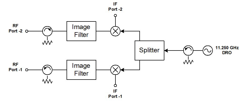
10 GHz Test Set - Block Diagram
10 GHz Test Set - Gain / Loss Measuement
10 GHz Test Set - Reflection Measurement
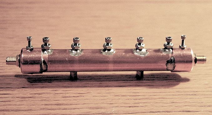
Image Filter for 10 GHz Test Set (click for more info)
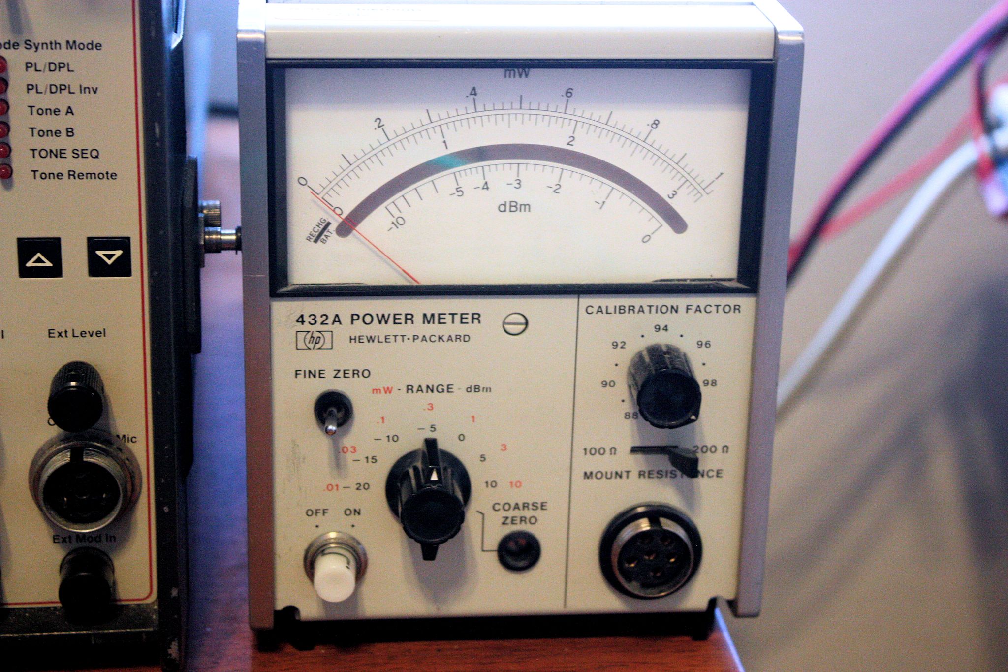
HP432A Power Meter
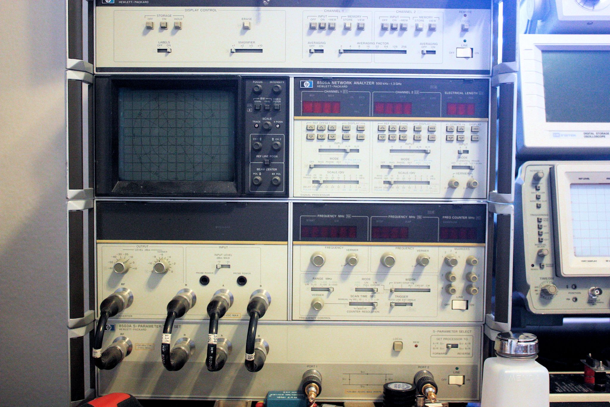
HP Vector Network Analyzer (good to 1.3 GHz)
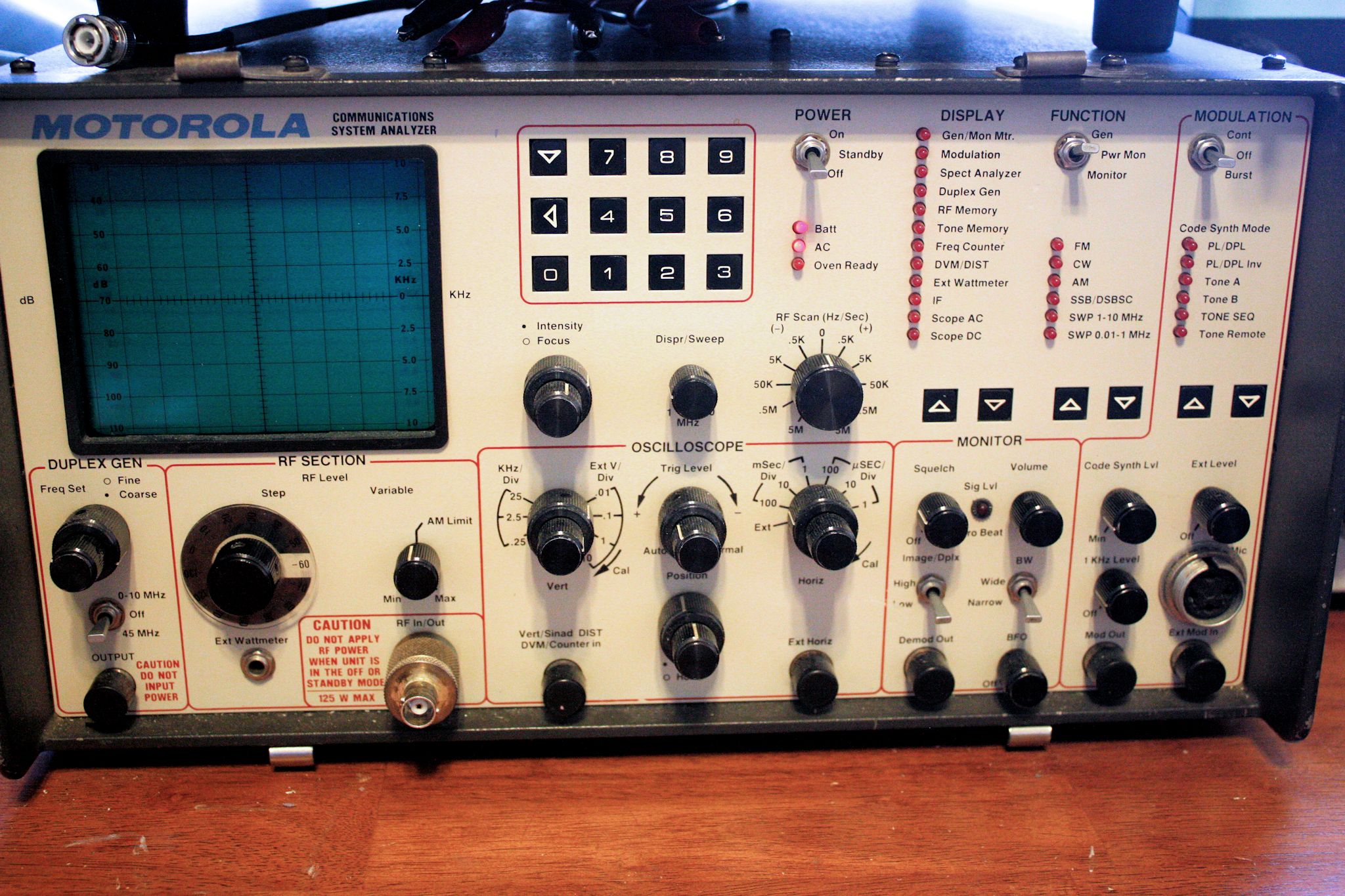
Motorola Service Monitor (source good to 1 GHz)
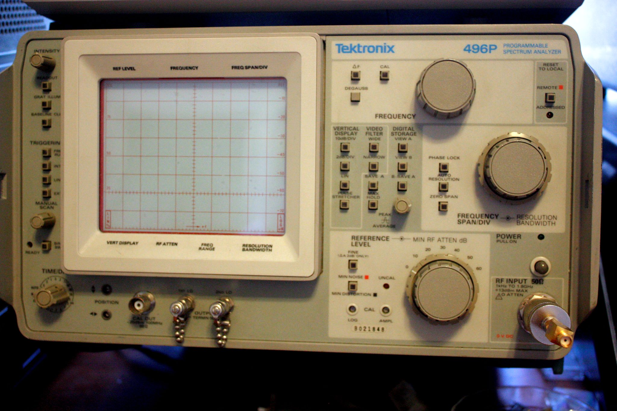
TEK Spectrum Analyzer (calibrated receiver (good to 1.8 GHz)